CWU RC Baja
3D Printing
The 3D printing has taken the largest amount of time in relation to any other process, including analysis and designing of parts. The parts have been printed in Hogue Hall and ABS was chosen for all the prints for its strength. Solid prints were chosen rather than a honeycomb interior as the weight is not a factor for the lightweight of ABS and the extra rigidness is wanted.

Figure 1 Lower Control Arm print
Part JLB-20-005 is being printed on a MakerBot 3D printer. This process of printing out two lower control arms took just over 5 hours.
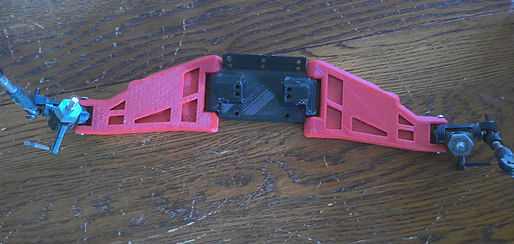
Figure 2 Shock Tower Base and Lower Control Arms
The front end, comprised of parts JLB-20-005 and JLB-20-011, is ready to be connected using pins that were machined on the lathe.

Figure 3 Chassis Mounts to Suspension
The figure above shows the left and right chassis mounts connected to the chassis-to-suspension mount.
Machining
The lathe was the most commonly used device as a large amount of the machining necessary was for shafts of different sorts. Aluminum was the chosen material for all metal parts for its lightweight and durability.

Figure 4 Tie Rod
Tie rods were used from a previous project and changed in the machine shop to fit this rc vehicle and female ball end joints were fitted on to the ends. This process was used for all tie rods involved in the project.
Construction
Figure 5 Partial Assembly of Front End
In this clip, the front left tire knuckle is being attached to the 3D printed lower control arm and a machined steering component is being further attached to the tire knuckle.
Drawing Tree
